Mfr Part # TL072HIDR
IC OPAMP JFET 2 CIRCUIT 8SOIC
Texas Instruments
Amplifiers Test Equipment Wired Analog Op-Amps
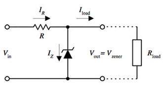
If you think back to your electronics I (or maybe II) class, you'll remember one of the really important properties of a voltage amplifier is that it barely loads your input—that is to say, it has an infinite input impedance. For example, if you want to create a simple 2.5V reference from a 5V source, you'd perhaps use a voltage divider. However, if you load the output of a voltage divider, the classic problem arises: you will effectively change the equivalent lower resistor, and thus the reference voltage will be lowered.
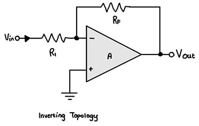
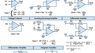
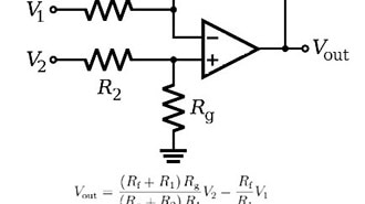
The typical solution here is to add a voltage buffering stage after the output. Such as the ubiquitous voltage follower op-amp:

This seems to work great, right? Well...
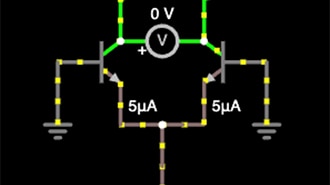
This really only works if the inputs of the op-amp draw zero current, which is what we are taught for ideal op-amps. In reality, however, they do draw some current. Instead of you taking my word for it, I'll prove it to you by showing you what a basic op-amp looks like under the hood:

For reasons that will soon be clear, I'm demonstrating this with a BJT differential pair.
Anyways, you'll actually see that when everything is all good and balanced, each leg carries the same current. However, if we remember our bipolar junction transistor (BJT) equations, we know that:
Ibase = Iemitter / (beta + 1), where beta is the current gain of the transistor.
The Falstad simulation uses a beta of 100, so:
Ibase = 5 mA / 101 ~= 49.505 uA, call it 50 uA.
This is your input bias current.
Let's consider that same voltage divider we had before:

Oh no! Our precious 2.5V has turned into 2.252V! If this is for a somewhat precise application, this may be intolerable!
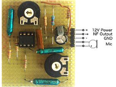
This pops up in other places. If you wanted to read from a sensor with a really high output impedance (like a microphone or piezoelectric device), say 10 Megaohms, the input bias current will cause a voltage drop high enough to completely smother your sensor signal in accordance with Ohm's law. Even if the input bias were 50 times less at 1 uA, you would have 10 Megaohms * 1 uA, 10 volts of drop! Your signal is completely gone.
First, we can remedy this a little bit. I would first check to see if I can decrease the overall resistance of the voltage divider. The general idea is that we want the bias current to be negligible compared to the divider current. This reduces the loading effect. Alternatively, you can say we are reducing the output impedance of the divider. The previous 10k + 10k divider current is nominally 5 V / 20kohm = 250 uA. Let's increase it to 1 mA overall, which would require two 2.5k resistors:

Now we have an error of 62 mV, as opposed to 248 mV from before. We can tweak this more at the cost of a higher power draw due to the higher divider current, and that may work fine for you. There are other neat tricks you can do, but the same issues stand: we don't always have the liberty of changing the impedance of our source, and sometimes its impedance is not precisely known, like for the microphone example.
The next step would be to ditch BJTs and use FETs! Remember that BJTs are current-controlled devices, while FETs are voltage-controlled devices. This is a very slight oversimplification, but perhaps that's a blog post for another day.
Since FETs are voltage-controlled, their input impedance is much greater -- they ideally have zero continuous gate current draw. However, this again is another failure of idealities -- the gate of a FET can be viewed as a capacitor, and capacitors have leakage current. This current is what presents as the finite input impedance of an FET op-amp. Let's compare a bipolar op-amp and a FET op-amp:
Contestant #1, the LM741, a classic BJT-based operational amplifier.
From the datasheet, we see the input bias current rating:

Contestant #2, the TL072. Another classic, the quintessential FET-based op-amp:

Clearly, the TL072 wins by a great margin. In the worst case, the TL072 has an Ibias that is 16 times less than the BEST case for the LM741.
I should mention -- both of these chips are pretty much ancient by today's standards, but they are still quite valuable for learning.
Like always, the bias current can vary greatly with other parameters, such as aging, temperature, loading, etc. Always consult the graphs in the datasheet!
In conclusion, input bias current is an important op-amp figure often missed by beginners. It represents the current the op-amp needs to draw from the input pins in order to function properly. If you don't account for this in your circuit designs, it can potentially cause you to fail to meet important design requirements or cause weird / unexpected behavior.
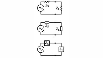
When designing amplifier circuits and analog circuits in general, always keep note of the various impedances in the system. Ask yourself: