Mfr Part # 4745
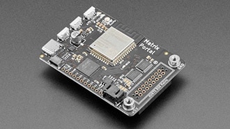
ADAFRUIT MATRIX PORTAL - CIRCUIT
Adafruit Industries LLC
License: See Original Project LED Matrix Arduino
Courtesy of Adafruit
Guide by Phillip Burgess
Overview
Adafruit_Protomatter is a C library (with Arduino and CircuitPython front-ends) for driving RGB LED matrices (colloquially called “HUB75” matrices but that’s a vague term and not entirely accurate). We already have one such library — RGBmatrixPanel for Arduino — it’s older code that works fine for AVR chips (and a couple others) but has some limitations.
This guide was mostly to assist with porting Adafruit_Protomatter to new hardware but has since been expanded with installation and basic use.
“Protomatter” was intended as a stand-in name until something better was decided upon, but we’d already moved in by that point.
In CircuitPython, it’s only seen by the sensible name rgbmatrix. But if working with the underlying C code or the Arduino library…sorry, you’re stuck with the awkward-to-type Protomatter name.
It originates in a quote from the character David Marcus in Star Trek III: “I used protomatter in the Genesis matrix.” Hopefully, the library doesn’t develop a similar reputation as “unstable” and “dangerously unpredictable.”
Protomatter was planned with newer hardware in mind and will not be back-ported to AVR — simply use the prior RGBmatrixPanel there if you need it. The new library takes a casual approach to some things and isn’t particularly RAM-efficient, a crucial concern on AVRs. What Protomatter does provide includes:
More flexibility in matrix chain width and height (RGBmatrixPanel only supports a few sizes)
More flexibility in pin selection (old code was specifically designed for an Arduino UNO shield)
Configurable bit depth, up to the maximum “565” color format used by Adafruit_GFX
Mostly doesn’t rely on esoteric peripherals — sticks with basic “PORT” GPIO and a timer interrupt. Some exceptions were made for ESP32-S3 and -S3
Mostly avoids cycle-counting
A likely candidate device for porting will have:
A reasonably fast 32-bit RISC core or similar (e.g., ARM, ESP32). Minimum we’ve used is a 48 MHz Cortex-M0+
One or more timer peripherals, 16-bit or better, with configurable period and with interrupts
GPIO with atomic bit-set and bit-clear registers, typically 32 bits wide…ideally tolerating writes to individual sub-bytes or words
RAM usage depends on matrix size, bit depth and GPIO pin selection. Minimum device we’ve used has 32 KB RAM (total for device, not all consumed by the library)
As currently written, Protomatter eschews the use of DMA or special peripherals beyond what’s described above. Goal is simply to get this working on a variety of devices with a minimum of fuss. We can tweak and optimize later.
Things You’ll Need
A datasheet or reference manual for the device being ported to
Hardware to test on. Having both a logic analyzer and a known-compatible-with-existing-devices RGB matrix is really helpful to verify that all signals are doing the right things at the right times
Text editor powered by tinymce.
To work with the Protomatter library in the Arduino IDE, access the Library Manager from the Sketch menu…
Sketch→Include Library→Manage Libraries…
Type “protomatter” in the search field at the top-right of the Library Manager window, then click Install for the Adafruit Protomatter library.
The very latest versions of the Arduino IDE automatically install other dependent libraries. If you’re on a slightly earlier version, search for “gfx” and install Adafruit GFX Library manually…
Adafruit_GFX is the same library that drives many of our LCD and OLED displays…if you’ve done other graphics projects, you might already be familiar! And if not, we have a separate guide explaining all of the available drawing functions. Most folks can get a quick start by looking at the Protomatter library’s “simple” and “doublebuffer_scrolltext” examples and tweaking these for their needs.
Some of the Protomatter examples rely on the Adafruit_PixelDust, Adafruit_LIS3DH and/or AnimatedGIF libraries…so again, search for and install those if not already handled automatically by Arduino.
If you’re using an Adafruit MatrixPortal board specifically, the MatrixPortal guide has a whole page for all of the needed libraries.
For Developers
If your plan is to adapt Protomatter to new devices, not just use it with existing boards, you’ll want to remove any Arduino-installed version of the library and download it from GitHub instead. This way you can submit pull requests for inclusion in future releases of the code.
You’ll find the Protomatter library at https://github.com/adafruit/Adafruit_Protomatter
and the GFX library, if any changes are needed, is at https://github.com/adafruit/Adafruit-GFX-Library
Text editor powered by tinymce.
Let’s look at a minimal Arduino example for the Adafruit_Protomatter library to illustrate how this works (this is pared down from the “simple” example sketch):
#include <Adafruit_Protomatter.h>

uint8_t rgbPins[]  = {7, 8, 9, 10, 11, 12};
uint8_t addrPins[] = {17, 18, 19, 20};
uint8_t clockPin   = 14;
uint8_t latchPin   = 15;
uint8_t oePin      = 16;

Adafruit_Protomatter matrix(
  64, 4, 1, rgbPins, 4, addrPins, clockPin, latchPin, oePin, false);

void setup(void) {
  Serial.begin(9600);

  // Initialize matrix...
  ProtomatterStatus status = matrix.begin();
  Serial.print("Protomatter begin() status: ");
  Serial.println((int)status);
  if(status != PROTOMATTER_OK) {
    for(;;);
  }

  // Make four color bars (red, green, blue, white) with brightness ramp:
  for(int x=0; x<matrix.width(); x++) {
    uint8_t level = x * 256 / matrix.width(); // 0-255 brightness
    matrix.drawPixel(x, matrix.height() - 4, matrix.color565(level, 0, 0));
    matrix.drawPixel(x, matrix.height() - 3, matrix.color565(0, level, 0));
    matrix.drawPixel(x, matrix.height() - 2, matrix.color565(0, 0, level));
    matrix.drawPixel(x, matrix.height() - 1, matrix.color565(level, level, level));
  }

  // Simple shapes and text, showing GFX library calls:
  matrix.drawCircle(12, 10, 9, matrix.color565(255, 0, 0));               // Red
  matrix.drawRect(14, 6, 17, 17, matrix.color565(0, 255, 0));             // Green
  matrix.drawTriangle(32, 9, 41, 27, 23, 27, matrix.color565(0, 0, 255)); // Blue
  matrix.println("ADAFRUIT"); // Default text color is white

  // AFTER DRAWING, A show() CALL IS REQUIRED TO UPDATE THE MATRIX!

  matrix.show(); // Copy data to matrix buffers
}

void loop(void) {
  Serial.print("Refresh FPS = ~");
  Serial.println(matrix.getFrameCount());
  delay(1000);
}
Breaking it down into steps…
Include Protomatter Library
First is to #include the library’s header file. This in turn #includes Adafruit_GFX.h, so you don’t have to.
#include <Adafruit_Protomatter.h>
Setting Up Matrix Pin Usage
The next few lines spell out the pin numbers being used. Using variables for this isn’t entirely necessary…one could just pass the same numeric values directly to functions…but it makes the code a little more self-documenting (and easier to adapt the same sketch for multiple boards — the full example code has #ifdefs for each board with different pin assignments). These also could be #defines or const if one wants to be all Proper™ about it.
Technical stuff for developers, skip this if you just want to use the library:
This is the one part of the Arduino code where some knowledge of the underlying hardware is required. rgbPins[] and clockPin must all be on the same GPIO PORT peripheral (e.g., all PORTA, all PORTB, etc.). The other pins have no such restrictions. Additionally, if the PORT has an atomic bit-toggle register, RAM requirements are minimized if rgbPins[] and clockPin are all within the same byte of that PORT*. They do not need to be contiguous nor in any particular sequence within that byte. If not within the same byte, next most efficient has them in the same upper or lower 16-bit word of the PORT. Scattered around a full 32-bit PORT still works but is the least RAM-efficient option.
* For devices lacking an atomic bit-toggle register…clockPin does not need to be in the same byte, but still must be in the same PORT. Should still aim for rgbPins[] in a single byte or word though!
With those constraints in mind, here’s what the code looks like for an Adafruit MatrixPortal M4 with a 64x32 pixel matrix:
uint8_t rgbPins[]  = {7, 8, 9, 10, 11, 12};
uint8_t addrPins[] = {17, 18, 19, 20};
uint8_t clockPin   = 14;
uint8_t latchPin   = 15;
uint8_t oePin      = 16;
The full “simple” example sketch has setups for a number of different boards and adapters.
Create the Protomatter Object
Next, still in the global area above setup(), we call the constructor. The Arduino library can only drive one matrix at a time (or one chain of matrices, where “out” from one is linked to “in” of the next), so we just have one instance of an Adafruit_Protomatter object here, which we’ll call matrix:
Adafruit_Protomatter matrix(
  64, 4, 1, rgbPins, 4, addrPins, clockPin, latchPin, oePin, false);
The Adafruit_Protomatter constructor expects between 9 and 11 arguments depending on the situation. The vital ones here, in order, are:
64 — the total matrix chain width, in pixels. This will usually be 64 or 32, the width of most common RGB LED matrices…but, if you have some other size or multiple matrices chained together, add up the total width here. For example, three chained 32-pixel-wide matrices would be 96.
4 — the bit depth, in planes, from 1 to 6 (see below). More bitplanes provides greater color fidelity at the expense of more RAM. A value of 4 here (4 bits) provides 16 brightness levels each for red, green, and blue — yielding 4,096 distinct colors possible.
1 — the number of matrix chains in parallel. This will almost always be 1, but the library could conceivably support up to 5, if the hardware driving it is set up precisely just so.
rgbPins — a uint8_t array of pin numbers, which issue the red, green and blue data for the upper and lower half of the matrix (sometimes labeled R1, G1, B1, R2, G2, B2 on the matrix input). The array should contain six times the prior argument…so, usually, six. If driving two chains in parallel, then 12 pin numbers and so forth. Obviously 12 pins won’t fit in a single PORT byte, and you should aim for the upper or lower 16-bit word in that case, for best RAM utilization. Three or more chains, doesn’t matter, but the pins all do still need to be in the same PORT.
4 — the number of row-select “address lines” used by the LED matrix (sometimes labeled A, B, C, etc. on the matrix input). 16-pixel-tall matrices will be three row-select lines, 32-pixel will have four, and 64-pixel will have five. Matrix height is always inferred from this value, not passed explicitly like width.
addrPins — a uint8_t array of pin numbers, one for each row-select address line, starting from least-significant bit. These do not need to be on the same PORT as rgbPins or each other…they can be mixed about anywhere.
clockPin — pin number which drives the RGB clock (CLK on matrix input). This must be on the same PORT register as rgbPins, and in most cases should also try to be in the same byte.
latchPin — pin number for “latch” signal (LAT on matrix input), indicating end-of-data. Can be any output-capable pin, no special constraints.
oePin — pin number for “!OE” signal (output-enable low, OE on matrix input). Can be any output-capable pin, no special constraints.
false — this flag indicates if the display should be double-buffered, better for animation at the expense of double the RAM usage. Since the protomatter example isn’t using animation, it passes false here…but if you look at the doublebuffer_scrolltext example, it uses true. A double-buffered display only modifies the matrix between refreshes, avoiding “tearing” artifacts. Optional. Default, if left unspecified, is false.
Not used here, an optional 11th argument supports “tiling” of matrices vertically. Horizontal tiling is already implicit in the first argument — if you had two 64x32 matrices side-by-side, you’d pass 128 there. But if you had four such matrices arranged 2x2, you’d still pass 128 for the first argument, but then add either 2 here (if cabling is in a “progressive” order) or -2 (if a “serpentine” order, where the second row of panels is rotated 180° relative to the first…the cabling is a little easier). The “tiled.ino” example demonstrates this. The concept is explained further in the CircuitPython LED Matrix guide…the same principles apply to the Arduino library, the arguments are just a little different here. Default if unspecified is 1 (no vertical tiling).
Also not used here, an optional 12th argument is a pointer to a hardware-specific timer structure…this is super exceedingly esoteric and not really used for now, but in principle would allow the library to work with other timer peripherals than the default.
Begin Protomatter Driver
Now, with the matrix object created, inside setup() we call its begin() function. It’s pretty important to look at the value returned, which is a ProtomatterStatus type:
ProtomatterStatus status = matrix.begin();
Possible return status values include:
PROTOMATTER_OK — everything is good, and the program can proceed (otherwise it should stop…the example code is not a good neighbor in this regard)
PROTOMATTER_ERR_PINS — the RGB data and clock pins are not all on the same PORT. Can’t continue, the library requires these pins in this layout
PROTOMATTER_ERR_MALLOC — couldn’t allocate enough memory for display. Can’t continue. This is usually an error that happens in the begin() function, but in extreme cases even the constructor could hit an allocation problem, but you won’t get this response until calling begin()
PROTOMATTER_ERR_ARG — some other bad input to function, distinct from PROTOMATTER_ERR_PINS. Exceedingly rare, might only happen if constructor failed
Draw Shapes & Text Using Adafruit GFX
Then we draw some stuff on the display. Any graphics primitive supported by the Adafruit_GFX library is available here.
Adafruit_GFX is the same library that drives many of our LCD and OLED displays…if you’ve done other graphics projects, you might already be familiar! And if not, we have a separate guide explaining all of the available drawing functions. Most folks can get a quick start by looking at the “simple” and “doublebuffer_scrolltext” examples and tweaking these for their needs.
Any color argument passed to a drawing function here is a 16-bit value, with the highest 5 bits representing red brightness (0 to 31), middle 6 bits for green (0 to 63), and least 5 bits for blue (0 to 31). It’s just how Adafruit_GFX works and is a carryover from early PC graphics and most small LCD/OLED displays.
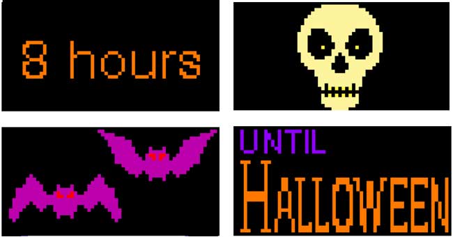
The effect of bit depth on image quality. Color values are always specified as full 16-bit “565” values but will quantize to coarser representations at lower bit depths.
Sometimes you might want to avoid 6-bit depth even if RAM permits it. Only green handles the full 6 bits, while red and blue are quantized to 5 bits. This can result in some colors or gradients having slight green or magenta tints to them. 5-bit depth is slightly blockier, but colors are more predictable.
matrix.drawCircle(12, 10, 9, matrix.color565(255, 0, 0));               // Red
matrix.drawRect(14, 6, 17, 17, matrix.color565(0, 255, 0));             // Green
...etc...
matrix.show(); // Copy data to matrix buffers
Notice though the call to matrix.show() at the end. Drawing operations have no immediate effect on the LED matrix, and instead are working on a buffer in RAM behind the scenes. Calling show() is required — it “pushes” the display data from that buffer to the matrix. You can call it after each drawing function, or group up a bunch of drawing commands with a single show() afterward to all appear at once. If you’ve worked with NeoPixel programming, it’s a similar phenomenon.
Since this program isn’t animating anything, it’s finished at that point and loop() could be empty.
Check Refresh Rate
For the sake of curious information though, the example shows the matrix refresh rate using getFrameCount(). This returns the number of frames since the last call to the same function, not the refresh rate…but if spaced about one second apart (delay(1000)), you get a fair approximation of refresh rate:
Serial.println(matrix.getFrameCount());
delay(1000);
The matrix refresh rate is influenced by so many factors…processor speed, matrix chain length, bit depth…that it’s difficult to accurately predict ahead of time, so this is a way to see what you get when changing different values in the constructor.
This is a subjective thing, but in broad terms 200 Hz or better should provide a solid image…any less and it starts to become flickery, so you might want a lower bit depth in that case. Conversely, refreshing too fast would waste CPU cycles that you probably want for other tasks like animation. The library does its best to throttle back and not refresh faster than practically needed.
Text editor powered by tinymce.
The Adafruit_Protomatter repository on Github contains all source code for the project. Create a new branch, to facilitate merging pull requests later.
Files there include:
The remaining files in the repository are for GitHub automation, the Arduino Library manager, Arduino examples and so forth. Probably won’t need editing, except for an occasional bump to the version number in library.properties.
Expanding arch.h For a New Part
Inside arch.h, you’ll find whole sections of code conditionally compiled in #if defined (and corresponding #endif) statements. You’ll want to add a new conditional check for your device — neither too specific (there’s usually some #define that broadly relates to a family of related devices), nor too vague that it accidentally compiles on an incompatible chip.
For example, anything in the Microchip SAMD51 family is covered by this:
#if defined(__SAMD51__)
  ...a whole bunch of code...
#endif // end __SAMD51__
Within each device family section, it’s further divided by (usually) a pair of #if defined checks, one to test if we’re compiling in the Arduino environment, another if CircuitPython…perhaps others in the future:
#if defined(ARDUINO)
  ...a whole bunch of code...
#elif defined(CIRCUITPY)
  ...a whole bunch of code...
#endif
This is because each environment has different convenience functions for certain operations. Arduino, for example, provides digitalWrite() for GPIO output. It’s different in CircuitPython, usually distinct to each architecture. The Protomatter code builds on these common operations. Additionally, in the Arduino setting, the library is usually attached to a specific timer/counter peripheral, set at compile-time, whereas in CircuitPython timers are a dynamically allocated resource…no telling what timer you’re using until run-time.
THEREFORE, each architecture and environment is expected to establish a known and fixed set of macros or functions providing these operations. core.c, which #includes arch.h, then goes about its business using only those known function names, never having to refer to device-specific hardware.
There are three groups of macros and functions: one related to GPIO, one related to timers, and one miscellaneous category. With just a few exceptions where noted, the following macros or functions are required.
The macros/functions are all prefixed with _PM_ (for Protomatter), sort of a brute-force namespacing of things (to reduce likelihood of collisions with user code) since we’re in simple C here.
GPIO-Related Macros/Functions
“Pin numbers,” as described here, refer to an environment’s particular indexing of pins, which might not map directly to a device’s PORTs and bits. Arduino digital and analog pins, for example, might really be scattered all over the place, but are exposed to the programmer as a tidy sequential list starting from zero. Other environments may have their own numbering system…but it’s always assumed there’s some numbering system. If not, you’ll need to make one up.
Timer-Related Macros/Functions
The (void*) argument passed to these functions is some implementation-specific representation of a timer peripheral. In some cases (such as on SAMD microcontrollers) it’s simply a pointer directly to a timer/counter peripheral’s register base address. If an implementation requires more data associated alongside a peripheral, this could instead be a pointer to a struct, or an integer index.
A timer interrupt service routine is also required, syntax for which varies between architectures.
Usually, the ISR needs to be related to a timer peripheral at compile-time, which is another reason why the Arduino implementation is always tied to a specific timer…other libraries, and the Arduino core itself, have their own ISRs for specific timers, we can’t take them all and dole them out on request.
Miscellaneous Macros/Functions
If adapting to some environment that’s neither Arduino nor CircuitPython: it’s easiest if the internal representation of an image in RAM matches what Adafruit_GFX is using: one 16-bit unsigned word per pixel, row major, no row padding. For example, a 64x32 pixel matrix will use 64x32 uint16_ts, or 4 kilobytes. The first word corresponds to pixel (0,0) at the top left.
Note that this is the drawing canvas into which points or lines or other primitives are drawn, but it’s distinct from additional space required by Protomatter, which must refresh the matrix plane-by-plane. Call the _PM_convert_565() function to process the simple canvas to the shuffled matrix representation and update the display.
If a different canvas representation is used, you’ll have to provide your own conversion function…_PM_convert_565() (and the functions it calls in turn) might offer some insights there.
Arduino and CircuitPython implementations already handle this.
Insights and Surprises
Troubleshooting by just looking at an attached matrix probably won’t yield much success. An oscilloscope or logic analyzer is really helpful. Initially, take a good look at the clock signal…this is the fastest signal the software has to generate (but mustn’t run too fast for the matrix, hence _PM_clockHoldHigh and _PM_clockHoldLow, if needed). Second, watch the !OE (output enable) signal…if the timer is properly configured and working, you should see the time interval between pulses double with each bitplane (e.g., N microseconds, N*2 microseconds, N*4, etc.). You should also see an obvious sequential bit-count among the row-select address lines.
A couple devices threw us for a loop…these problems were surmountable, but worth specifically mentioning here as it may be relevant to future porting efforts…
STM32
PORT bit-set and bit-clear registers do not correspond to 32-bit ports. Instead, a single 32-bit register has 16-bit set and clear sections. At least the bits are contiguous, and PMportSetRegister() and PMportClearRegister() can just return pointers to the upper or lower half of the register. Constrained to 16 bits, this does mean that STM32 is limited to a maximum of two concurrent matrix chains.
ESP32
A little peculiar in that the bit-set and bit-clear registers aren’t entirely atomic. If two set or clear operations occur in rapid sequence (as happens in a couple places in the library), the second has no effect. One solution would be adding NOP instructions, but this is kludgey in that it doesn’t automatically handle faster CPU variants if those come along in the future. Workaround was to always alternate bit-set with bit-clear, using a bitmask of 0 for the second operation. This waits for the first operation to “latch,” and the second has no effect…we can follow up with another bit-set and it works reliably now.
ESP32 needs the timer ISR function (and any sub-functions it calls) in RAM rather than flash. This is done with an IRAM_ATTR attribute on a function and broke our rule of “keep any device-specific code out of core.c.” So…if any other devices also require in-RAM ISRs, and if they use an attribute other than IRAM_ATTR…one should #define IRAM_ATTR to whatever attribute is required there, so that section of the code will handle either case.
ESP32-S2 and -S3
GPIO set/clear operations are somewhat slower than the original ESP32, which would result in a flickery display, so these two make an exception to the GPIO+timer rule and rely on chip-specific peripherals. On the ESP32-S2, the Dedicated GPIO peripheral is used. On ESP32-S3, the LCD controller peripheral. An interesting side effect of this, because the ESP32 family has very flexible pin-MUXing capabilities, is that any pins can be used to drive the matrix…there’s no specific order or continuity required.
Text editor powered by tinymce.